
Quadruped Part 1 - Motor Control
Once again it’s been a while since I last posted! I have a lot to catch up on for my quadruped so time to get started!

I posted a handful of CAD screenshots a while ago and the design has just been more flushed out since then.
The idea for this quadruped was inspired by Mini Cheetah and Stanford Doggo. The design is overall clearly a derivative of Mini Cheetah (in terms of hardware, software, firmware) because it’s great and I’m most familiar with it but it utilizes a coaxial drive mechanism for the hip and knee that is inspired by the Doggo. This allows the hip and knee motors to be located before the leg entirely.

I started this project by searching on Aliexpress and finding a promising motor. I was aiming to build a quadruped smaller than Mini Cheetah and used Ben’s original leg as inspiration. I considered building motor modules for convenience but decided that with all my factors (mostly controller choice and wanting to keep costs low) I could make the robot more compact if it was more integrated and less modular. In the future now that I’m getting more used to spending my own money on projects I think the additional cost of making things modular is worth it in terms of convenience.
After finding a candidate motor, I ordered 1 to inspect it and mechanically it looked great. It’s labelled as a 5010 motor based on its stator dimensions. Next step was to figure out how to control it.

Normally I would have preferred to use a Mini Cheetah controller but due to the chip shortage the ICs I would need are hard to come by. I started on two possible candidates for replacement controllers I could use for my quadruped. The first which I documented on my blog was designing a new controller based on the F3 and a hardware DRV chip. I had made some progress on it but hadn’t really started on firmware yet. The other was using a COTS hardware controller and just doing firmware. The benefit being I wouldn’t have to assemble 12 controllers myself for the quadruped. I decided to go with the latter.
Earlier this year my friend Chetan sent me a link to an interesting ST example ESC that is based on the G4 aimed for quadcopter enthusiasts. It only cost $18 though and was actually quite nice. It uses all ST ICs, the FETs have low RDS, it has a CAN transceiver, and its already assembled (most important part). I bought a handful assuming someone in my friend group would eventually write firmware for it. Fast forward to working on the quadruped and I came across this project on Github which was someone essentially developing Mini Cheetah controller style firmware for this super cheap G4 example ESC. I decided to use that firmware as a starting point and so I ordered the same 14 bit PWM encoders they used and got started.
The main controller difference between these G4 escs and the Mini Cheetah ones is that there is no integrated encoder. So there are an extra 3 wires that need to go from the motor to the controller. That being said, the controller can now be mounted anywhere.
Here’s the new controller on the right and my knockoff Ben controller on the left. You can see they’re about the same size (also a side note the left half of the G4 controller is just a programmer and can be snapped off but I like the ability to conveniently reflash the controllers and haven’t done so).

The first thing I did with the Github firmware as a starting point was to try and understand it. I redid the communication protocol to match the Mini Cheetah style messages to start. Next I proceeded to butcher the internet firmware to add things like gear ratios, zeroing, and change the parameters for the current loop. In the future I would like to add the ability to measure pole pairs, resistance, and inductance in calibration but for the moment I held off on that.
I realized I needed to retune the current controller in a pretty scary way. The internet firmware used just high gain P to control the current and it seemed to work fairly well at steady state which is all that I saw at the time. I would command Iq and it would match at the CAN update rate. Velocity mode also worked well. But then occasionally when I would command large position jumps, the motor would just start spinning wildly.
I started logging the data here in the tabs labelled “Death” (because this wild behavior managed to kill 2 controllers). In looking at the log I saw the current was not tracking the command anywhere near fast enough and was lagging enough for the motor to overshoot, rollover position and have all sorts of awful behavior. You can watch me tune the current loop in the proceeding tabs on the same sheet. Because this is a first order system I used just PI (also because this is the way Ben did it). I wanted to keep the I term relatively low to avoid windup and I wanted P to be as high as I could get it for more current loop bandwidth. Here’s an example set of plots as I was tuning.

Position step. The commanded current blip is a logging bug (I was logging over serial at 16khz)

I was balancing high P gain for high current bandwidth at the expense of overshoot. In the future I can definitely balance this out using the I gain better but I wanted to move on with this “good enough” firmware.
I also want to learn how to choose more optimal gains and so I measured the resistance and inductance of the motor using simple methods.
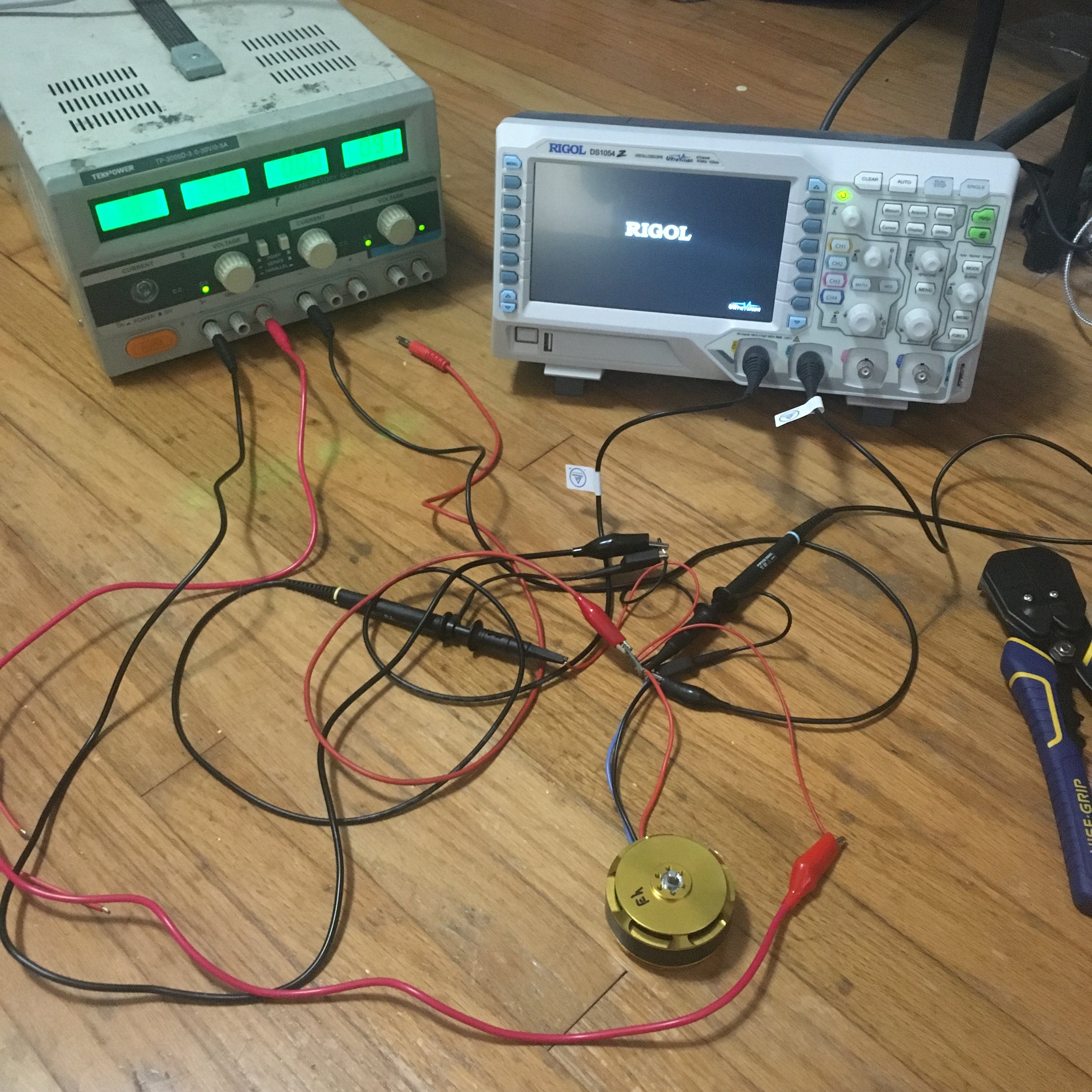
I applied a voltage step by plugging in the power supply and monitoring current (using a hall current sensor) through the phases and voltage applied using the scope. Blue is voltage, and yellow is the voltage proportional to current.

I estimated phase resistance by using the steady state current and voltage with ohms law. I estimated inductance using the time constant of the current ramping up. Scope data and values are here.
The inductance of this motor was quite high so it makes sense that Ben’s gains for the U8 motor current loop just did not work.
Next I did some quick torque testing with a lever arm and a scale. I had an estimate for kt of the motor based on the kv but I always prefer to take data when possible.

I was surprised by how high the kt for this motor was but I’m happy. Perhaps I received the wrong kv motor or my method of estimating kt from kv was wrong (I don’t think it’d be off by this order of magnitude). Either way I have a measured kt and I am quite happy with this motor performance.


This post is getting long so I’ll end it here and continue with mechanical bits in the next one!