
Brushless Swerve 2021

When I made my first swerve out of old 3lb Battlebot motors almost a year ago, I had in my mind the goal to build something more exciting and bigger when I had access to more tools and/or parts (both mechanical and electrical at the time).
My first instinct was to build a swerve cart that I could sit in, but, after thinking more, I realized that the coolest part about swerve to me is the mobility of translating while rotating, and you lose that cool factor when in the reference frame of the robot.
Some time in 2021 I had found some promising skateboard hubmotors on Aliexpress and like any motor I buy overseas, once the test motor showed up, if I planned on using multiple in a project ever, I needed to order them right away to avoid design changes and shortages.
A similar situation occurred with ebay 6374s and so I was sitting on 8 motors for a brushless swerve with no other concrete plans. They were sized to handle a human if needed, although as you can tell I opted not to do so.
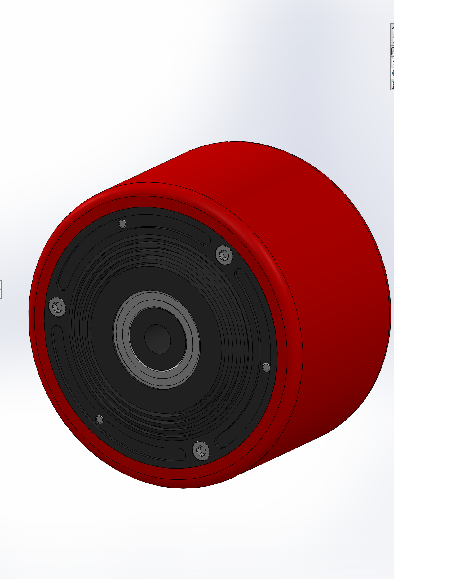
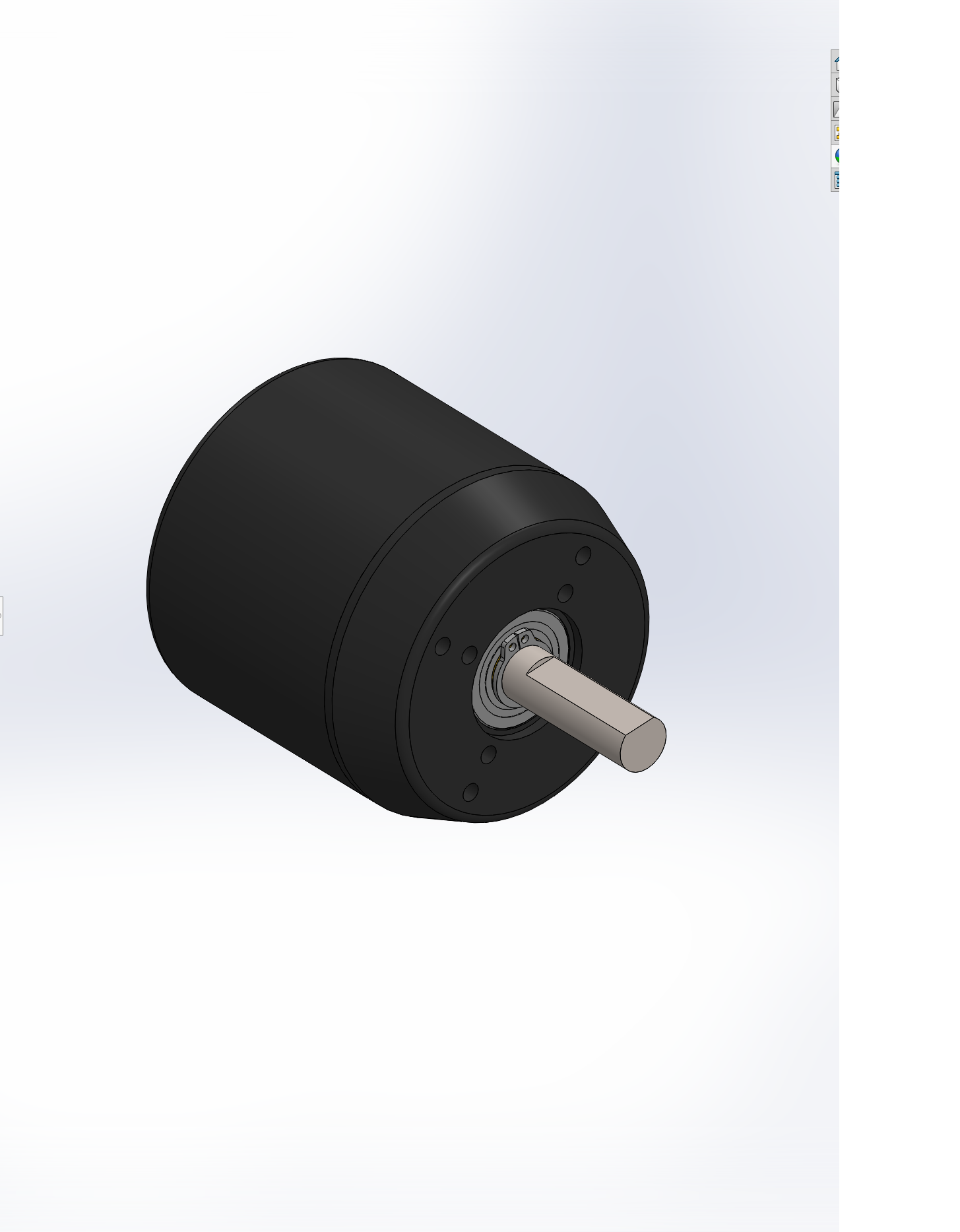
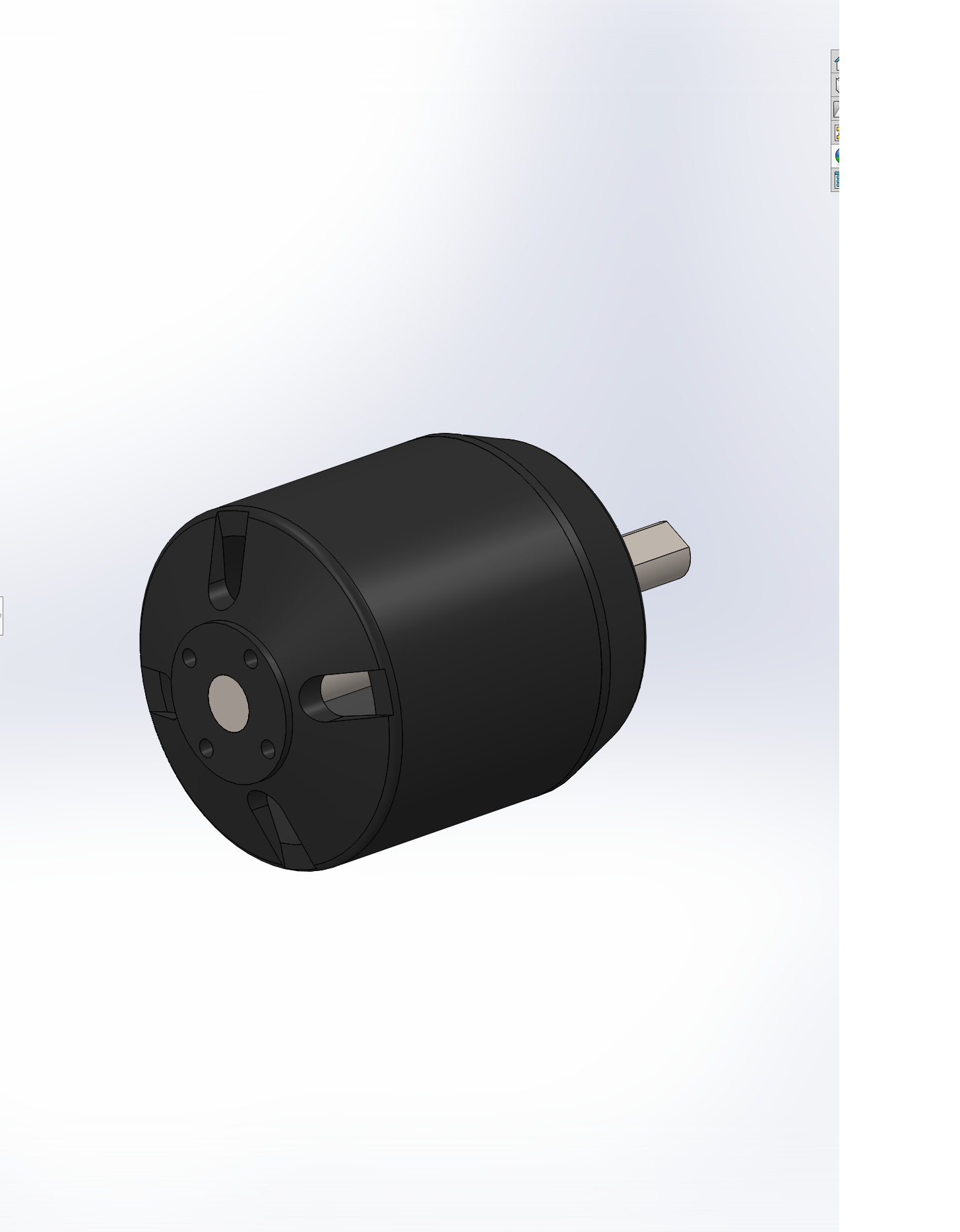
One thing that I do that sometimes helps motivate me to use parts for a project is I make detailed models of the motors so that when inspiration hits I don’t need to spend time on these details.

My biggest problem with making the swerve at this time was the chip shortage, and how it related to motor controllers. The motor controllers I used for my quadruped were a bit undersized (and quite annoying to use with their extra wiring needed because of the external encoder), and I hadn’t made much progress on my F303 port of Ben’s firmware.
Towards the end of 2021 I managed to acquire some T motor drives from a friend, which are based on Ben’s motor controllers (and run the same firmware), and I knew where I wanted to put them.
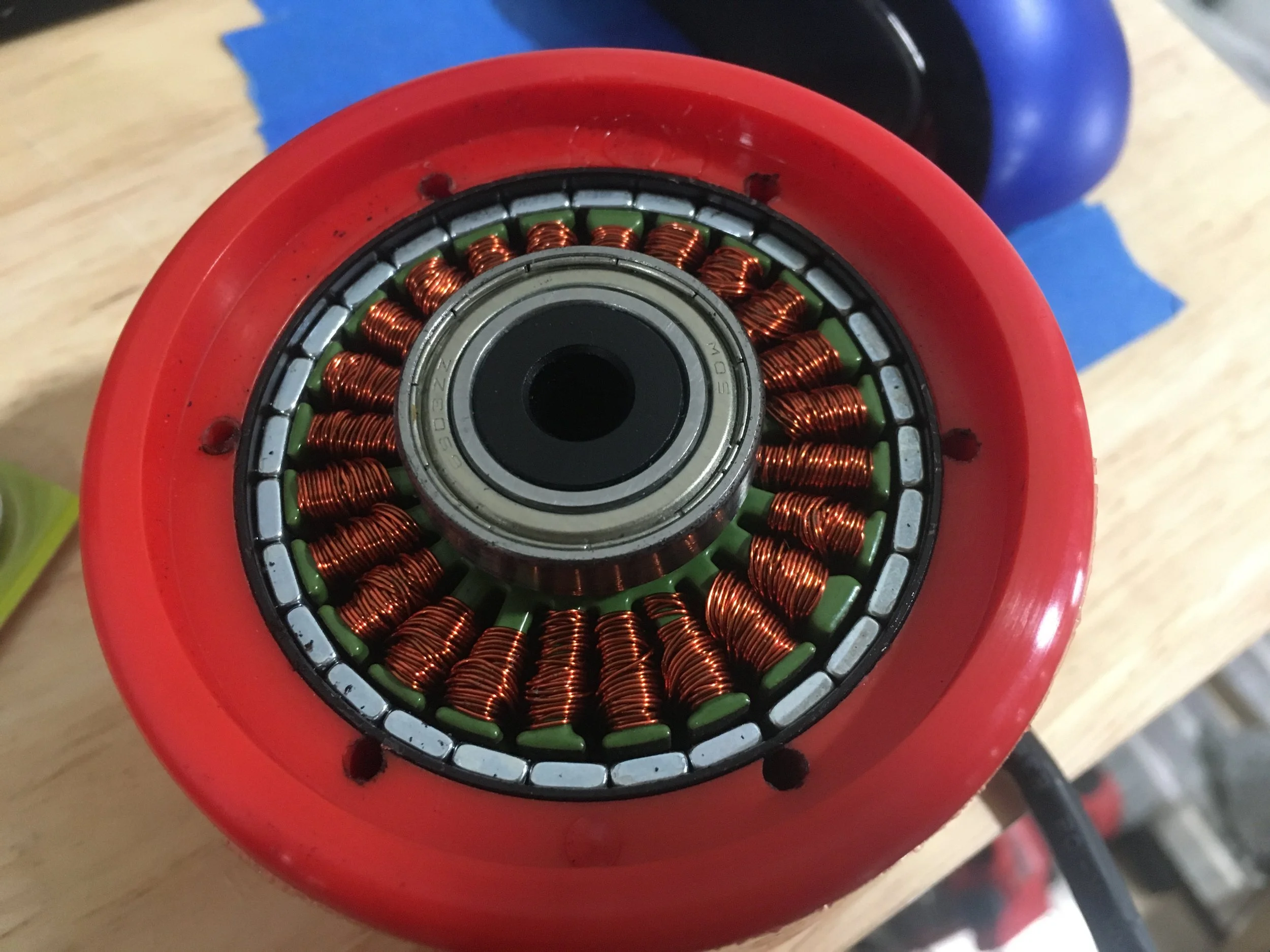
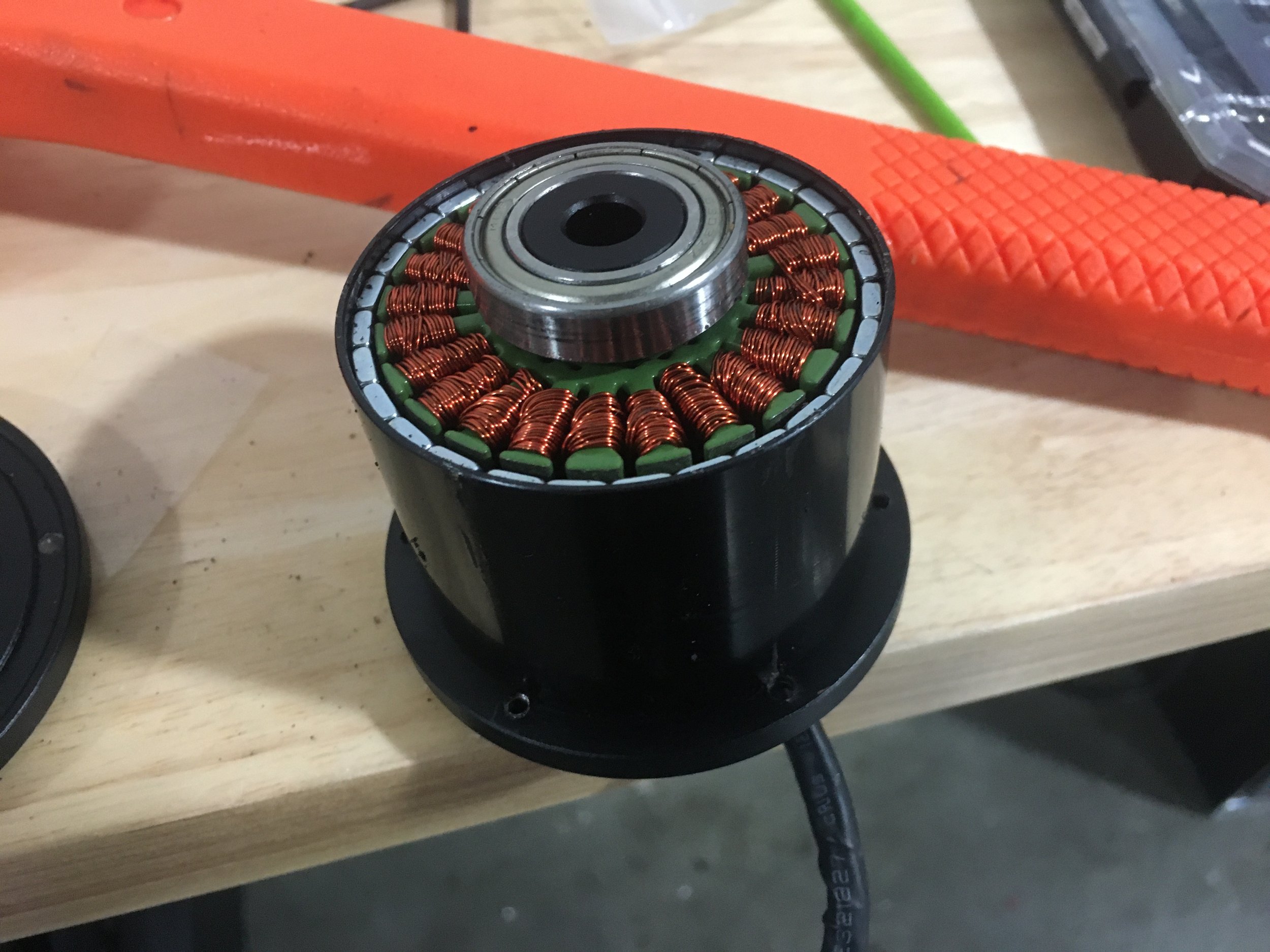
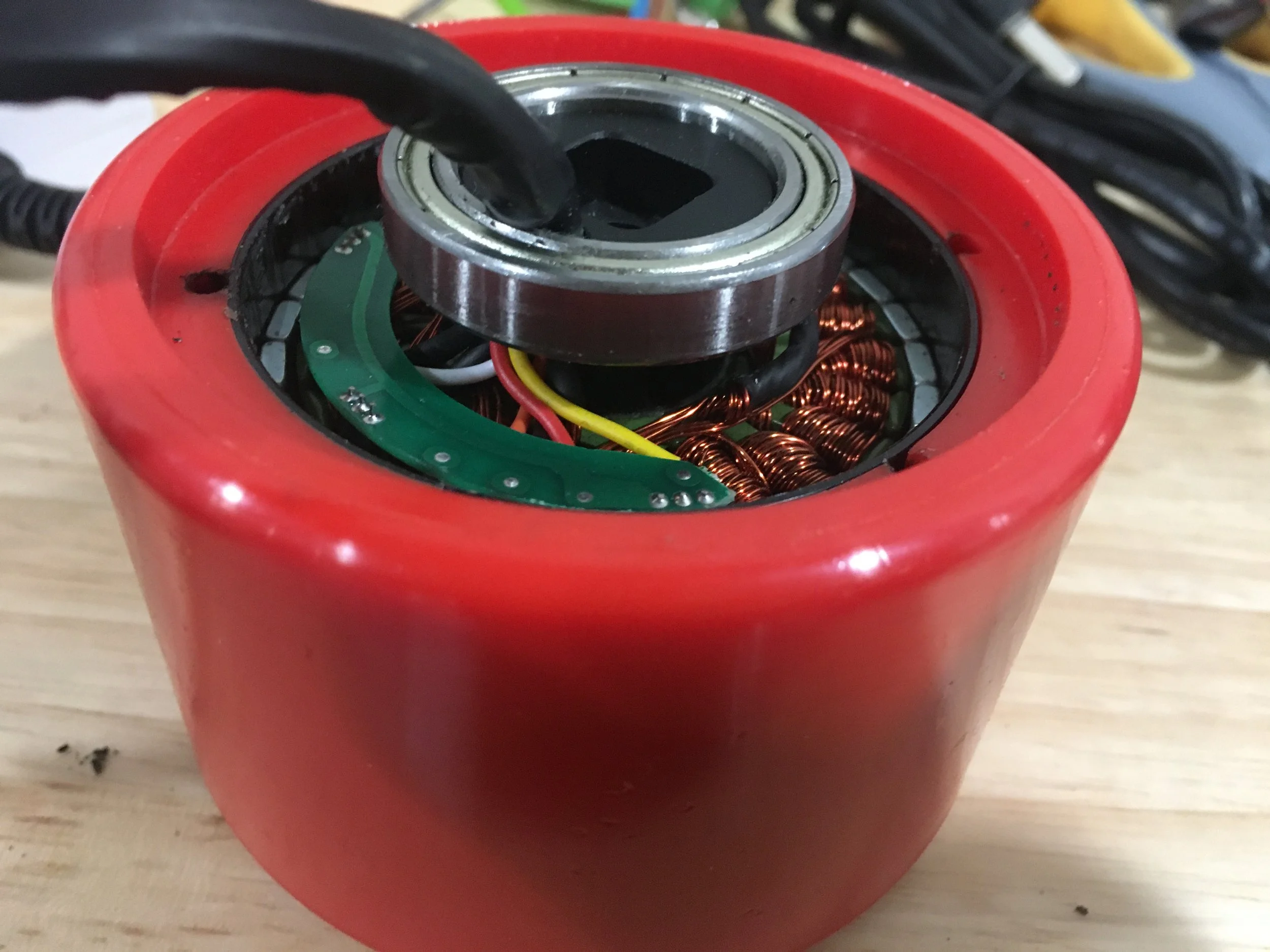
As my hubmotor choice would suggest I was going to have the wheel motor in the pivoting pod and so I found some cheap ebay slip rings to use.
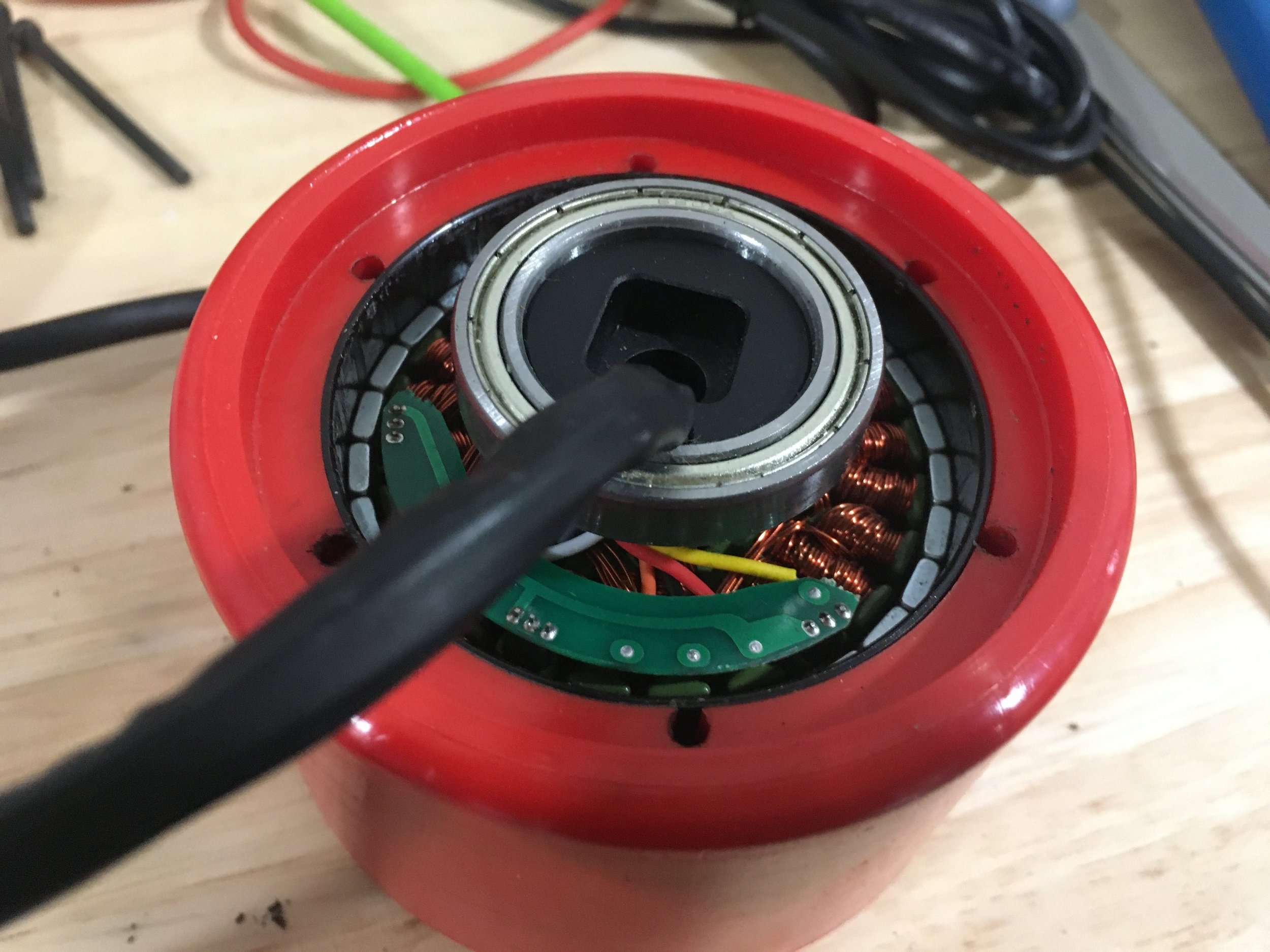
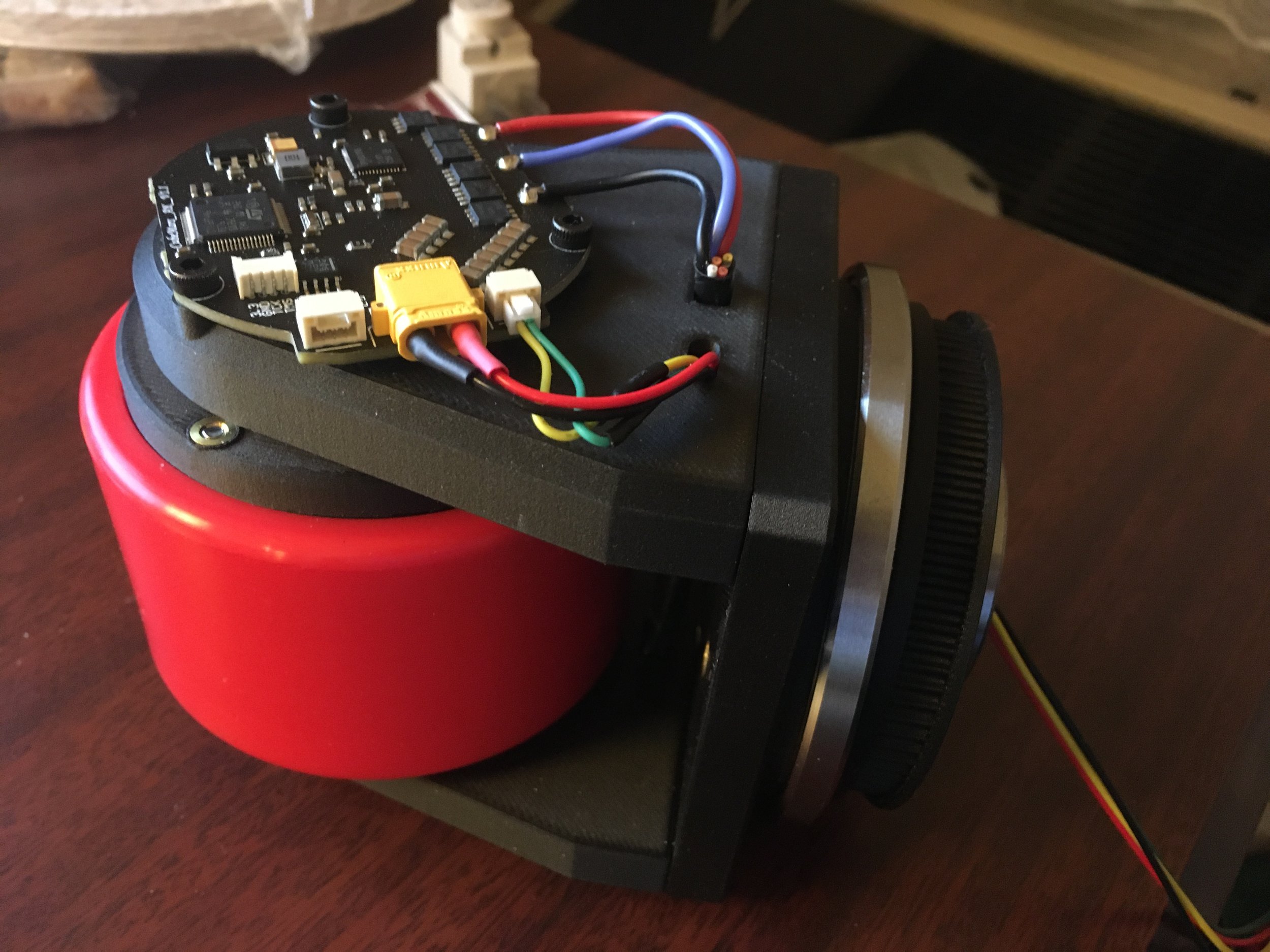
I started by figuring out how to mount the controller to the hubmotor. It was a little awkward because the hubmotor was not designed to have an encoder magnet mounted to it (it has halls built in) but I made do by adding more bearings.

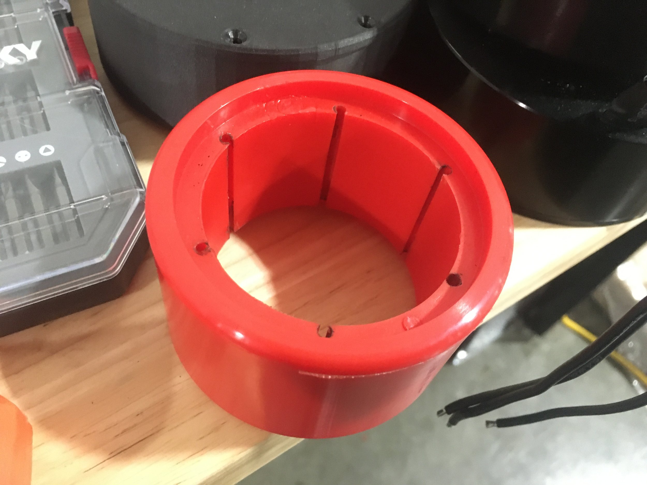
Now I was able to print the wheel module assembly.
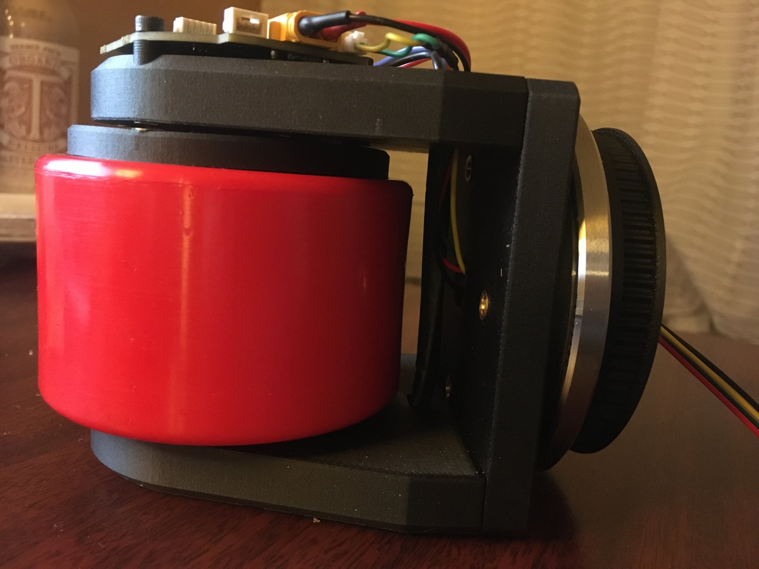
A bit more printing later and the rest of the module appeared
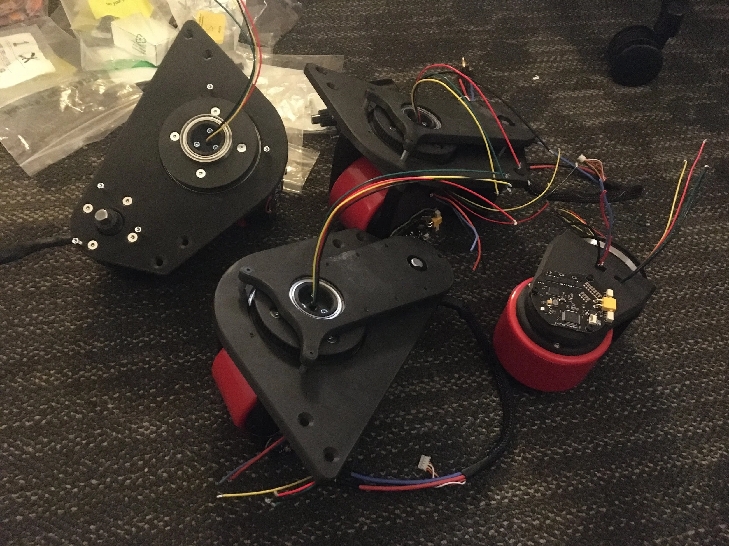
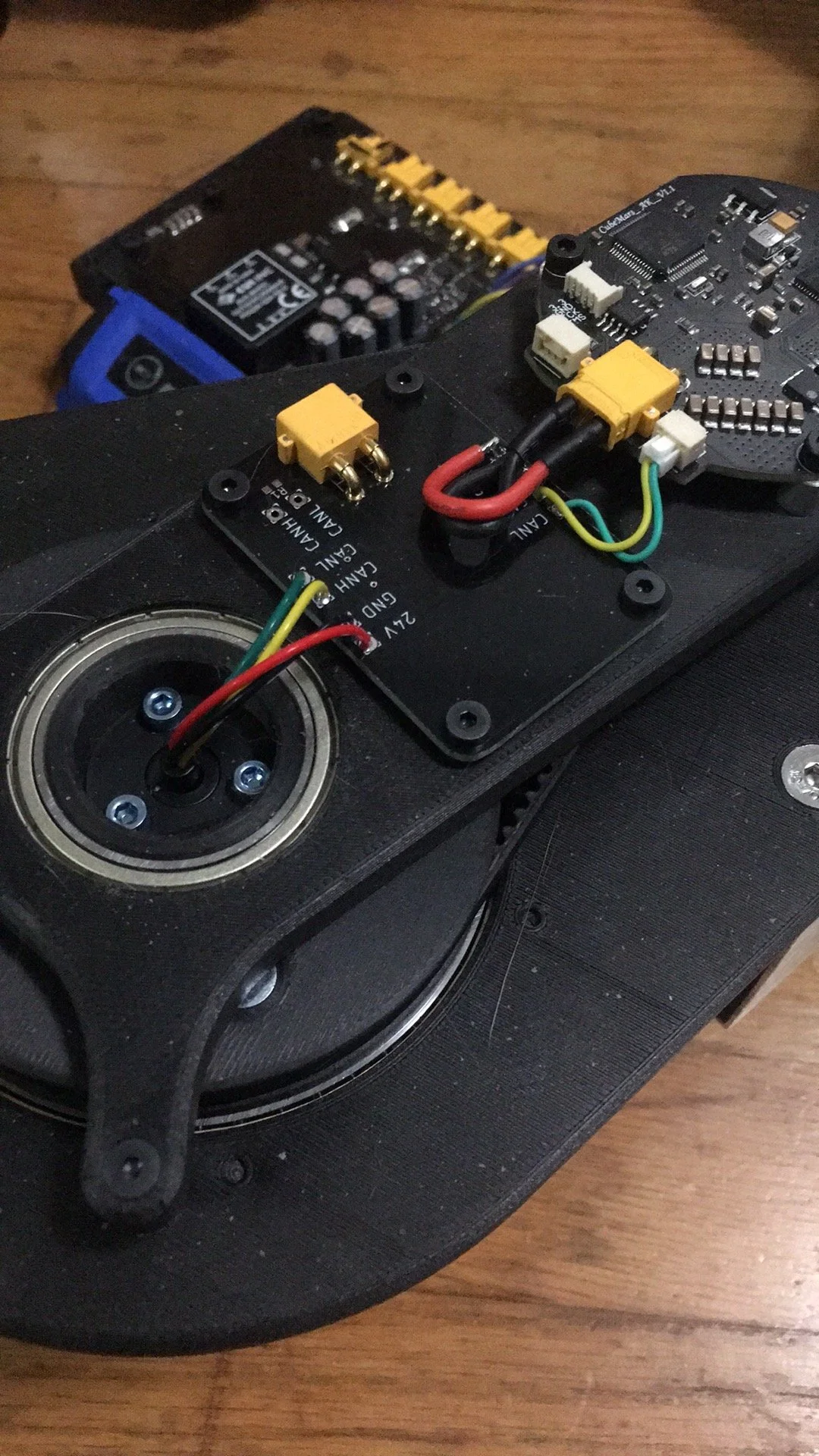
To make my wiring life easier I made these simple module distribution PCBs that provided 24V and CAN to both motors in each module (plus an optional termination resistor).
There was a bit of a mistake where I forgot to include CAN in and CAN out on those distribution PCBs so the wiring got a little messier when I had to solder 2 wires to the CAN pads, but it wasn’t a big deal.
The rest of the frame was made of Versaframe (throwback to my FRC roots) cause it was surprisingly cheap and convenient.

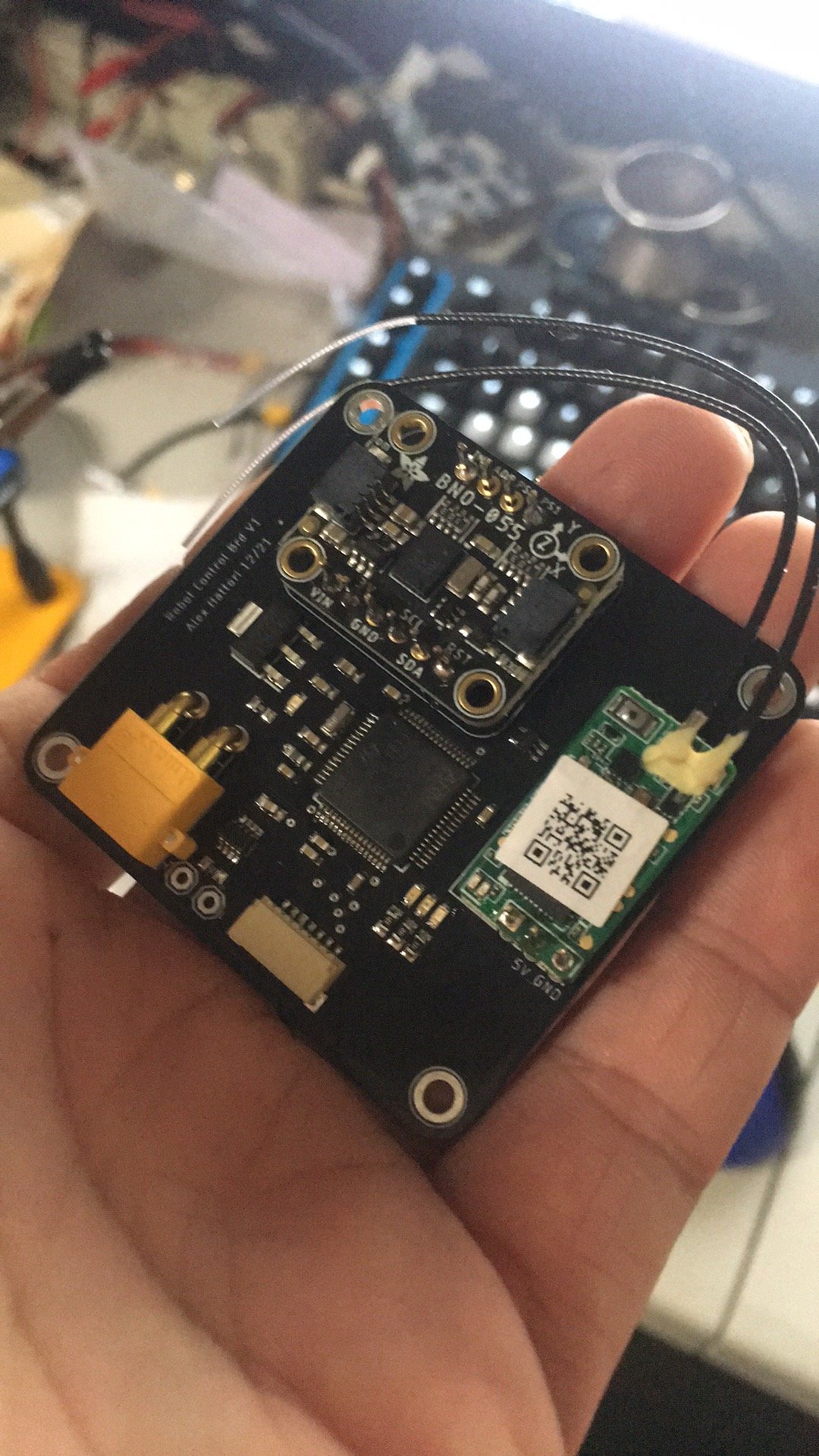
I also made a quick control PCB that has an F446 (stolen from a Nucleo cause tough times), IMU, receiver, and CAN transceiver.
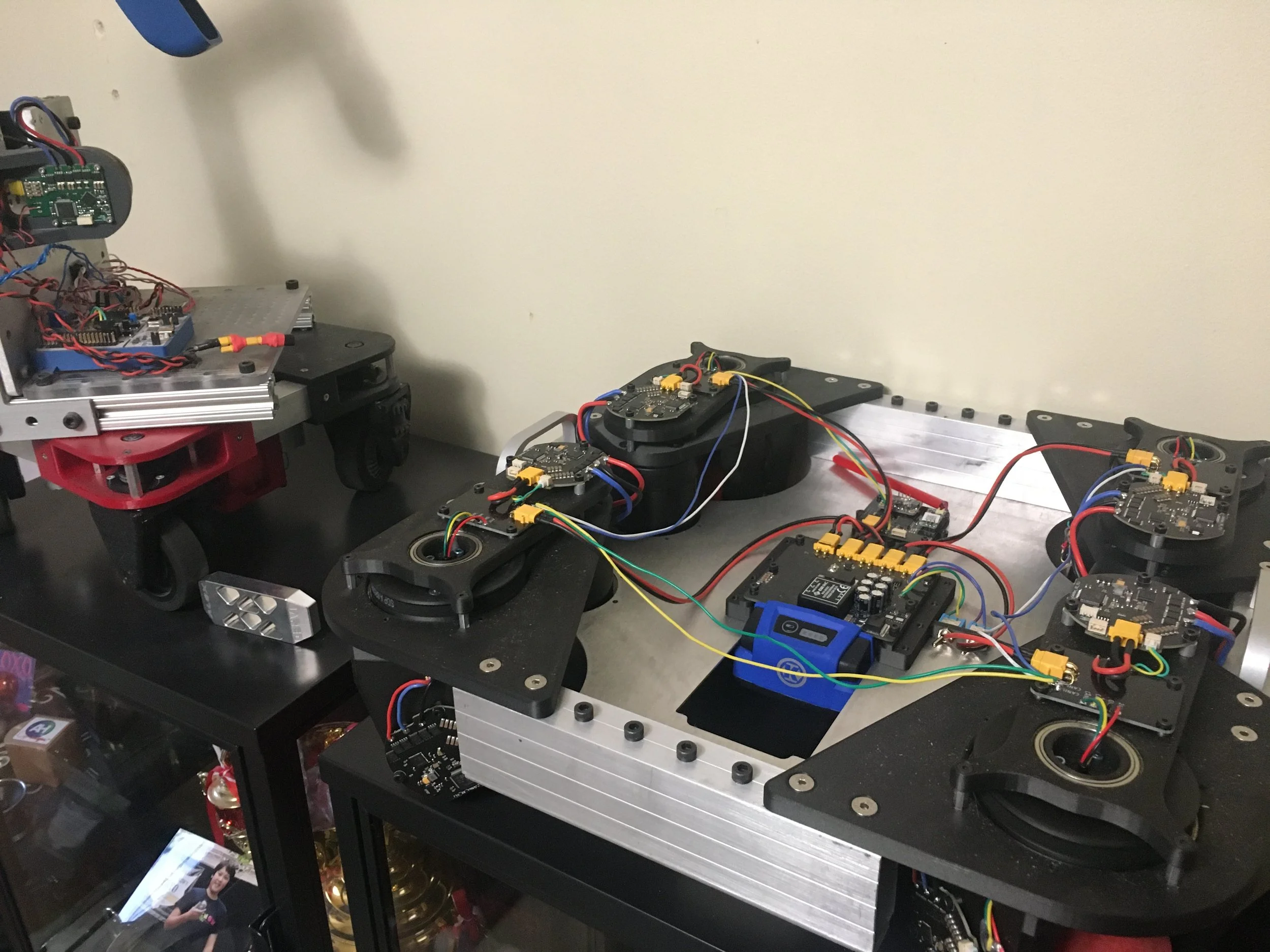
And with that, the robot was basically done. Here it is with the OG printed swerve in the background for scale (ignore the ball yeeter on top). As you can see I used the same modified Mini Cheetah power supply board and Kobalt battery that has become quite common on my projects.
Firmware wise, I started with the printed swerve code as a baseline but ended up rewriting most of it because this time all the computation was done on one microcontroller (instead of 1 per module and 1 main one). It has the same features like modules never pivoting more than 180 degrees, ramping up the wheel speeds with angle error, headless mode, etc.
My only complaint at the moment is that it doesn’t take into account acceleration limits and because the robot is quite light, the wheels pivot quite quickly and the robot skitters along in the direction it was going because it doesn’t have enough traction.
Here’s a video of the finished robot. The first 10 seconds are just in standard mode, and then I flip into headless mode and do the classic spinning while translating that drew me to swerve.